This week we learned about the different techniques of 3D Scanning and tested the capalities of our 3D Printers to make something that can only be done using additive manufacturing.
Requirements
- Test the design rules for your 3D printer(s)
Group Assignment
Individual Assignment
- Design and 3D print an object (small, few cm3, limited by printer time) that could not be easily made subtractively.
- 3D scan an object, try to prepare it for printing (and optionally print it).
Softwares 💻
- Fusion 360
- PrusaSlicer
- Meshmixer
- KIRI Engine Application
- XYFull Control Gcode Designer
Group Assignment
To design anything you have to first know the capabilities of your manufacturing method since today's week is about 3D Printing there's a plethora of resources and videos and interesting tests to make but Let's start with the basics shall we?
Features
| Specifications | Prusa MK3S+ |
|---|---|
| Nozzle Diameter | 0.4mm |
| Build Volume | 210 X 210 X 250 mm |
| Filament Diameter | 1.75mm |
| Firmware | 3.14.1 |
| Handbook | Here ver: 3.18 |
Tests
Since Amr, me, and Doaa are 3D junkies we were exctied to test the lab's 3 Prusa(s). I tested the angle test, the bridging test, and a temperature tower for TPU which turned out a 🍝. I downloaded the tests from the lecture notes and began slicing them on PrusaSlicer. Each was given a time-slot of about 1 hour to 3D print our tests, so I had to resize the test a little.
First I had to do the slicing and I scaled the tests down to 75% to print within the time range
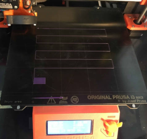
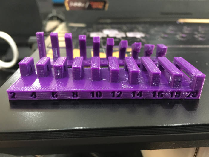
Bridge test results the bridging turned out very neat maybe at the end it starts to slag so slightly. The slag started at 20 but again when I scaled the part 75% thus this when I measured was 15mm instead and the slag was not very noticeable
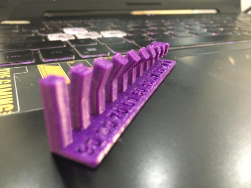
Angle test results. 30 deg angle is the maximum angle
Then I made a The temperature tower for the TPU filament spool we had. So, I used this design. In PrusaSlicer, I right-clicked on the vertical slider then add a custom G-code at
the start of each section of
the tower. The G-code I added was this
M104 S"temperature".
The results was a spaghetti tour. I suspect there's a problem with the filament. Please check Doaa's successful temperature tower. I think the problem was in the filament.
3D Printing
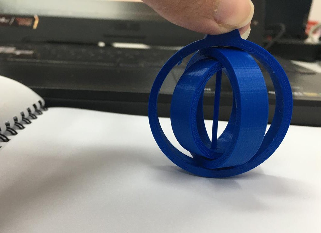
Gyroscope
To warm up our hands we were asked to design a keychain that can not be easily made using a subtractive manufacturing method. The first things I thought of making was a cavity inside a cube or anything that falls under the same concept for example, gyroscopes or something that can be print-place meaning it's printed in one go on the 3D printer yet once you remove it you'll see it can move semi-freely because of some tricks in the design especially the concept of leaving spaced cavaties between the parts you want to move. We call this trick Clearance.
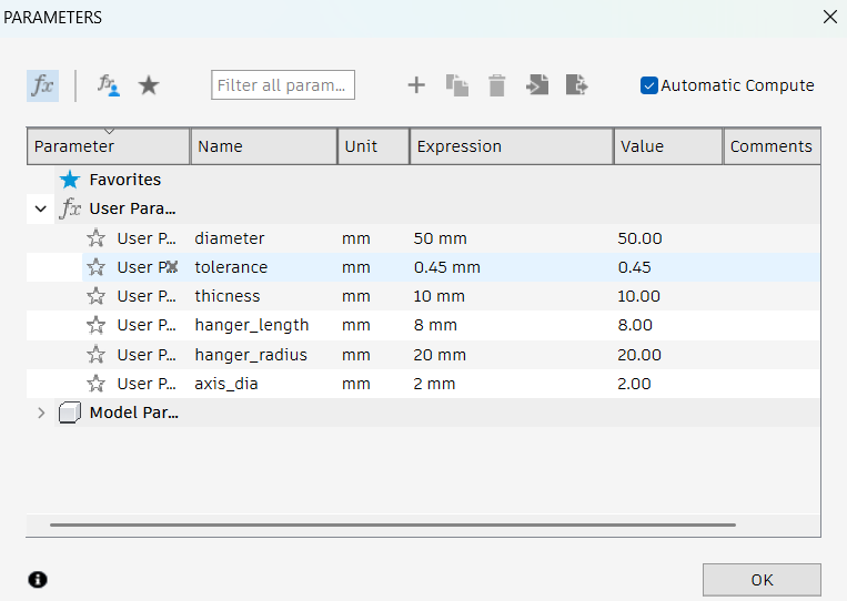
Doaa tested the clearance so I used those values to create a parameter in Fusion360 and gave it the value of 0.4.-
Step 1
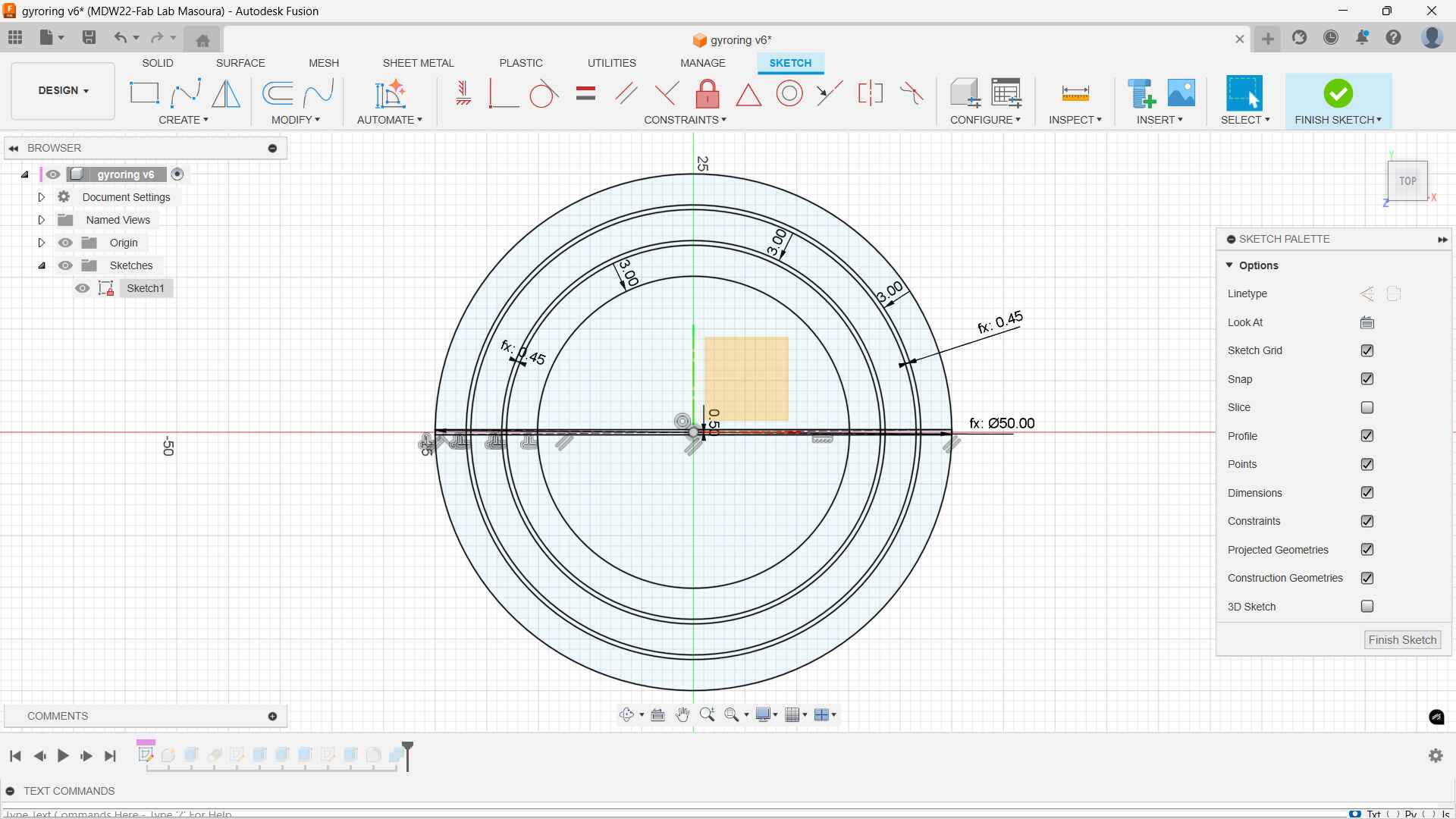
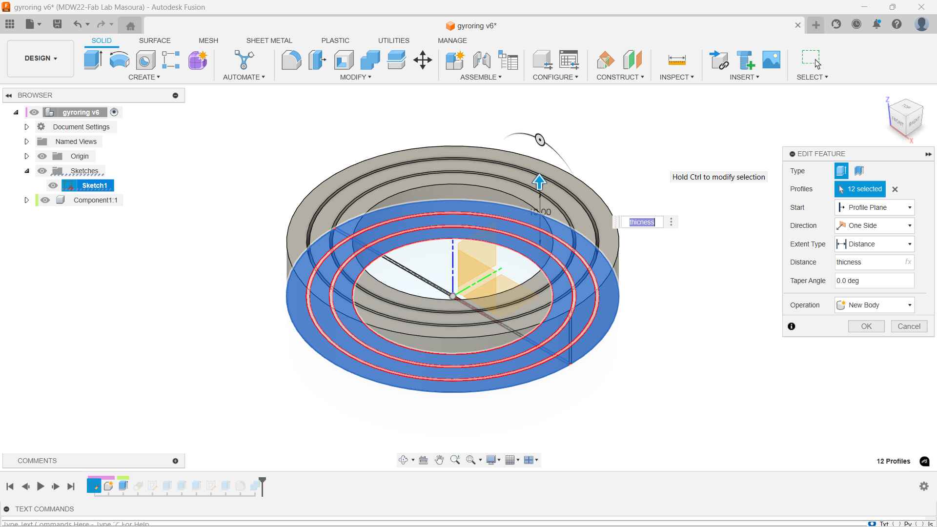
Created a sketch of a top view for the gyro. making offsets based on the clearance we tested. I began to draft the main parameters I will use to make my design parameteric
Then I extruded with the "thickness" parameter as the distance.
-
Step 2
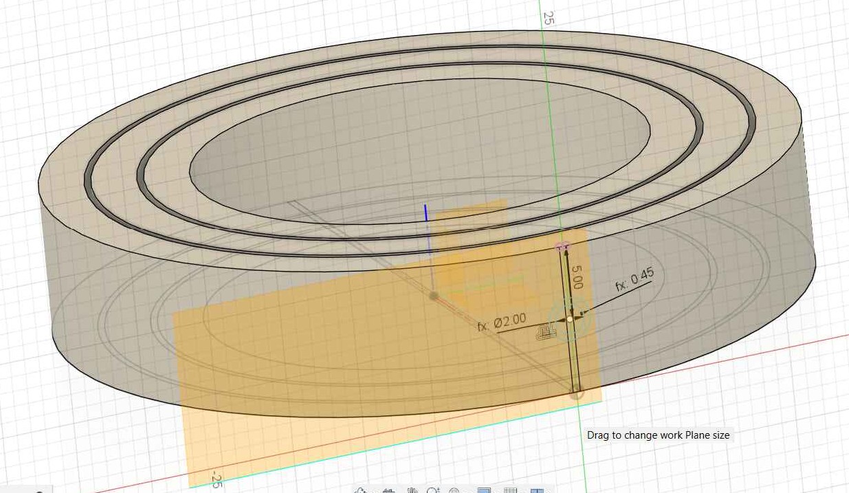
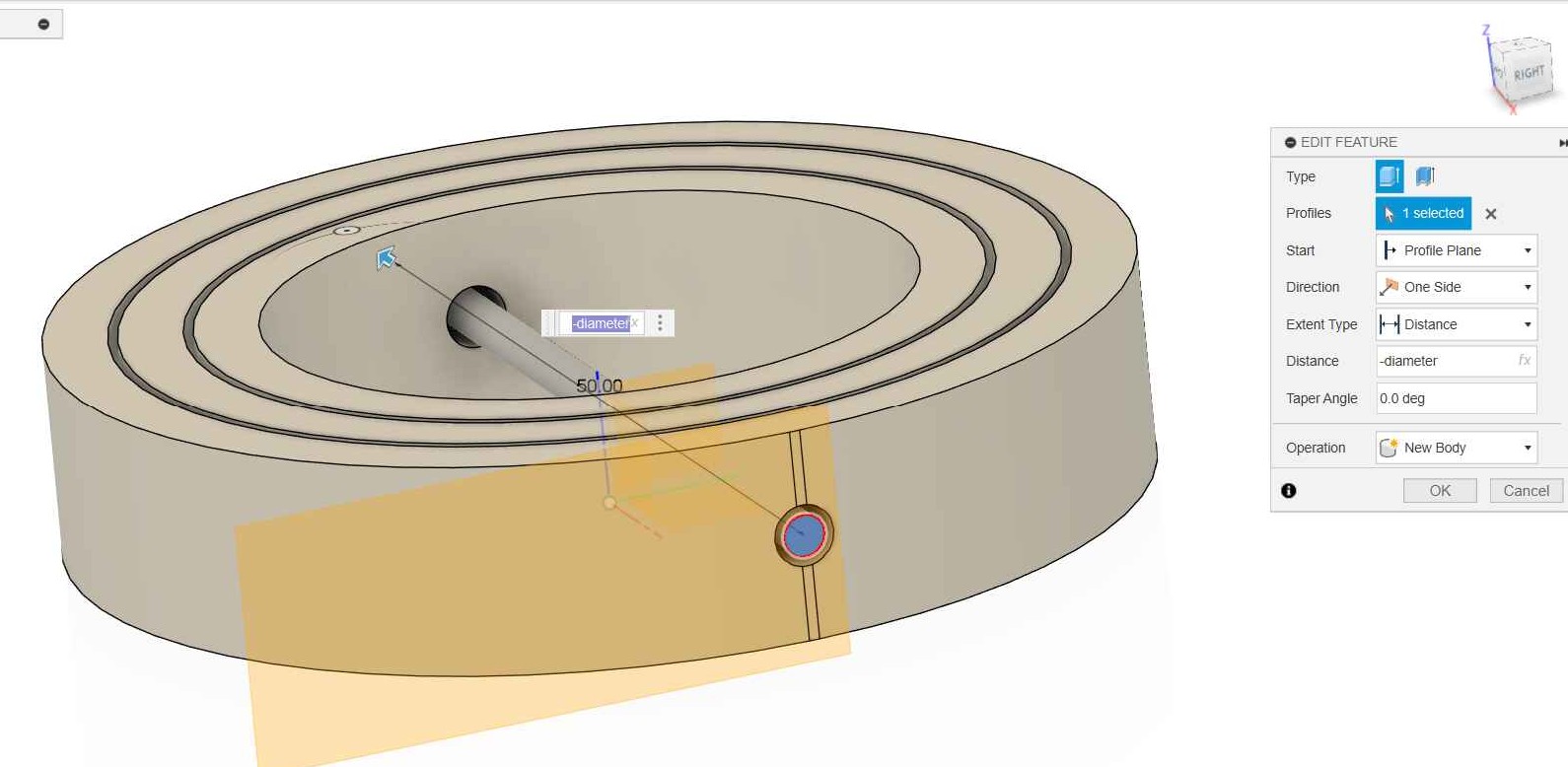
Then to create an axis in the middle, I created a tangent plane and sketched two cocentric circle. One to extrude cut and the other to be extruded to be the axis.
-
Step 3
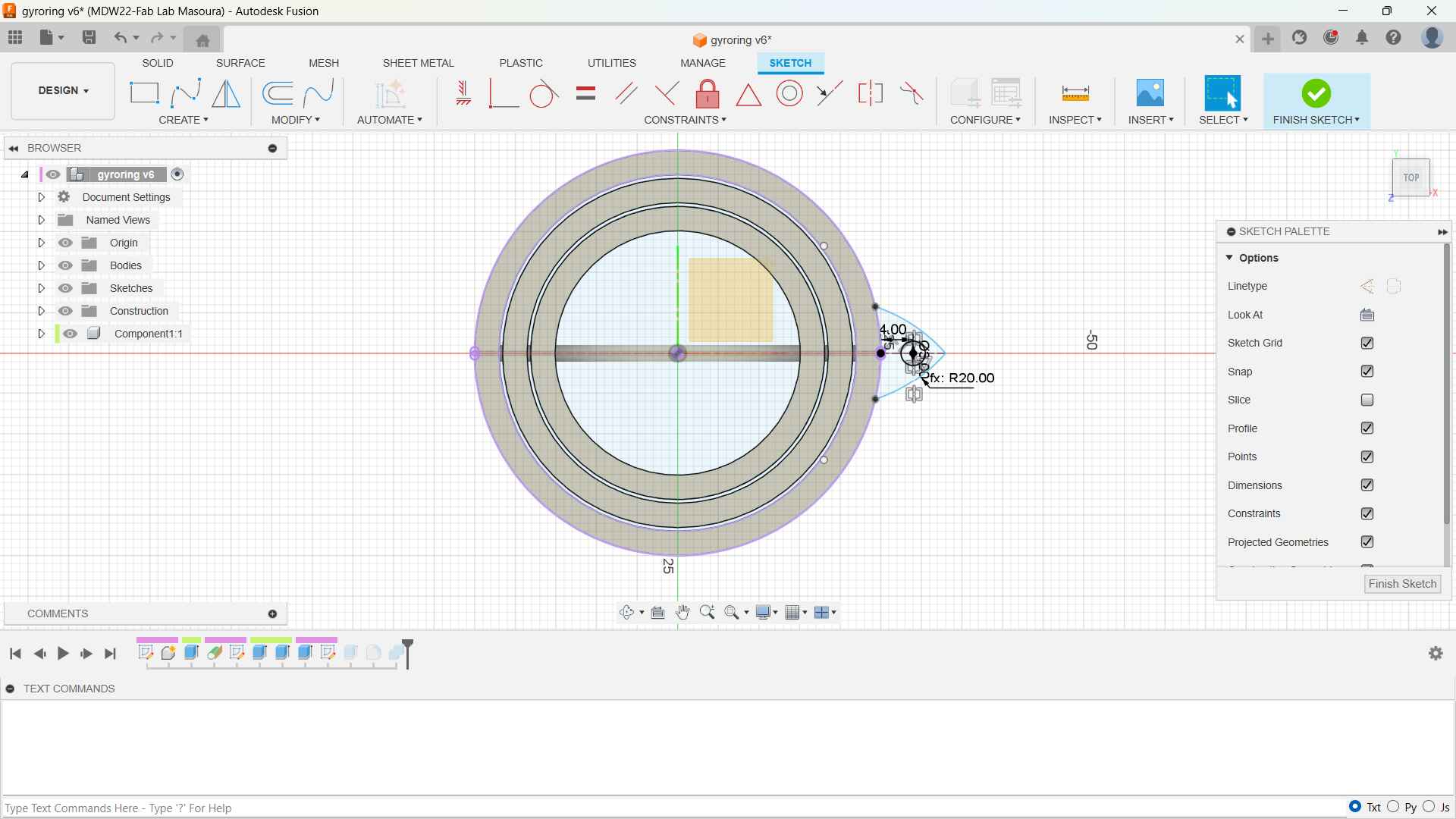
Then I created the keychain hook. And Voila!
I went and sliced it in prusaSlicer and Voila again!
Future Plans.
I got inspired by the Brigham Young University's complaint mechanism and I would have love to recreate some of their designs but there's always a next time.
Flexible Mesh
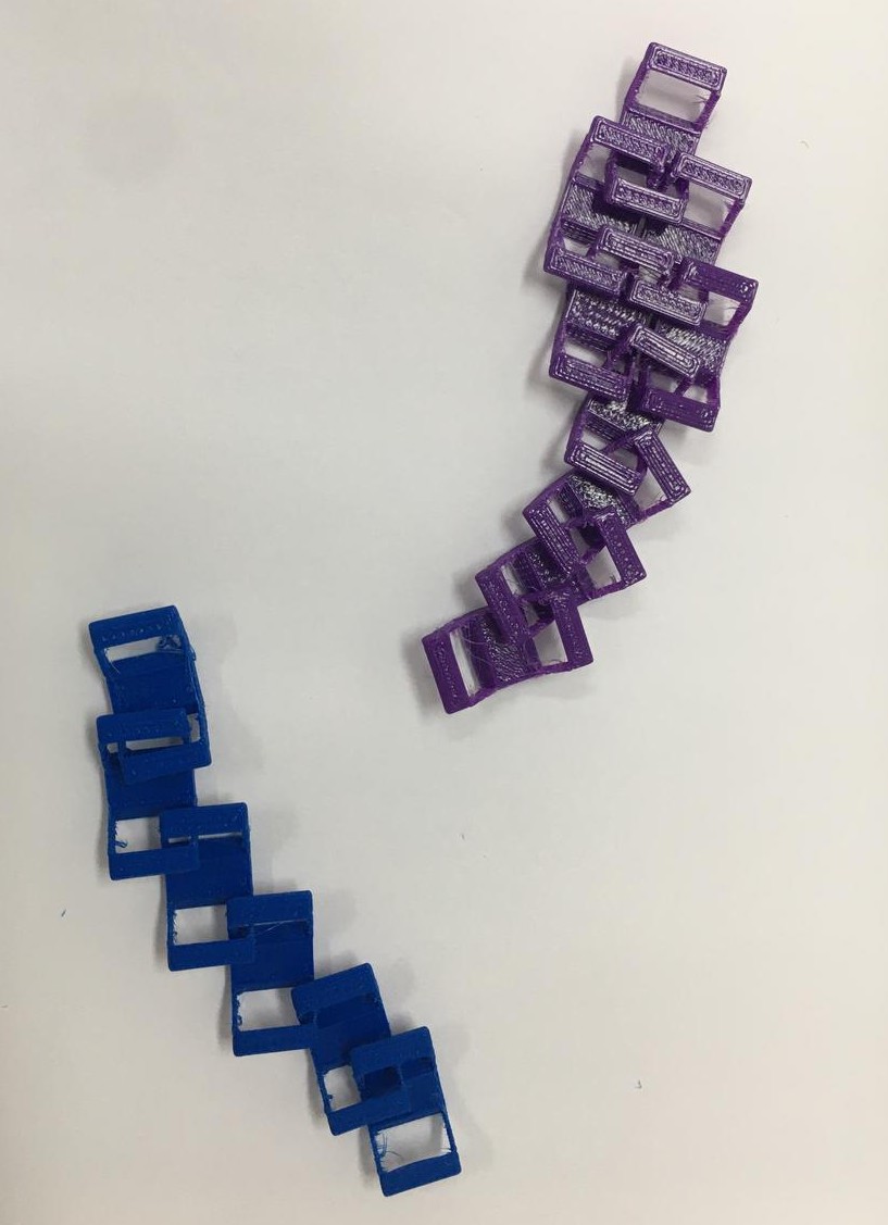
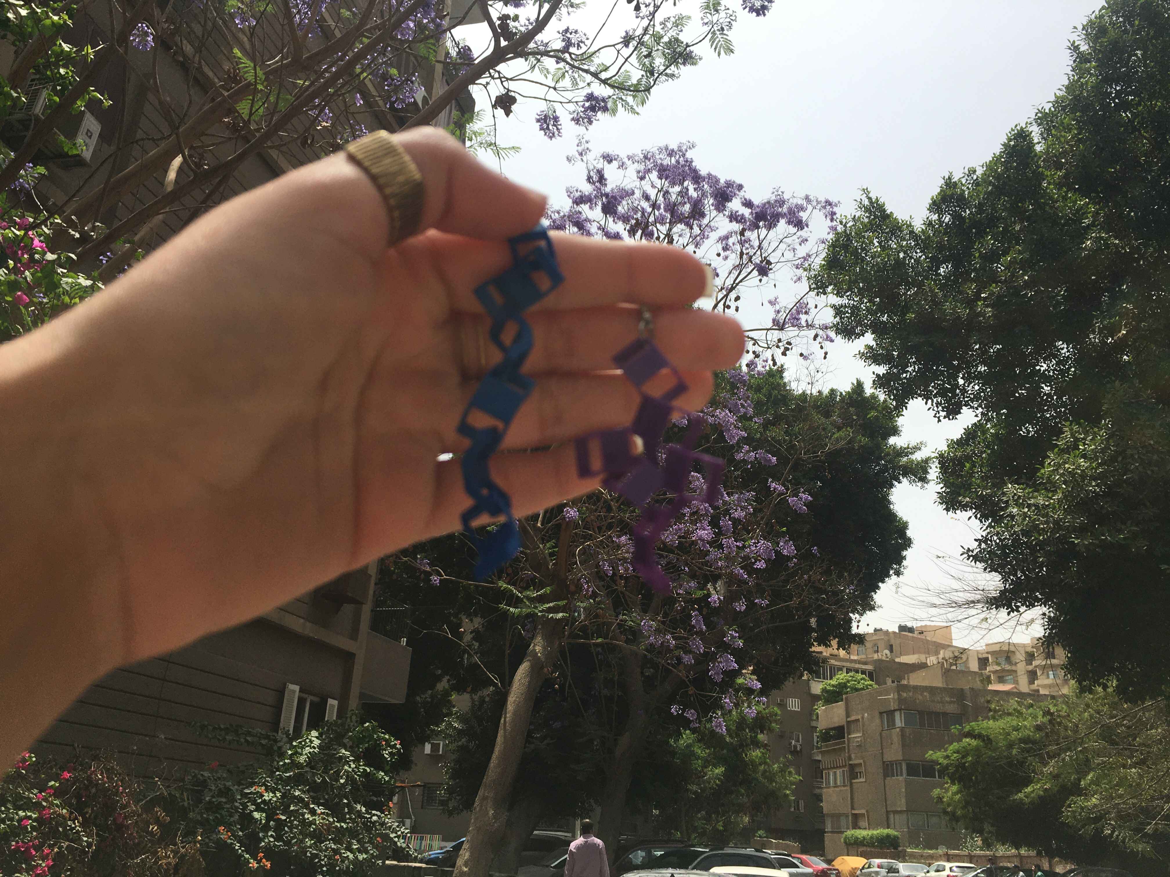
I got the inspiration to create a flexible mesh from this 3D printed walllet that we have at the lab
The idea behind a flexible mesh is simple you create an pattern of objects that seem to be walking arm in arm, the object that linked to one another via an hole something like chains and you repeat this pattern to create fabric-like mesh. It also depeneds on the clearance and the angle test.
The design Process
I looked at the wallet thourghtly and tried to visualize it wss designed from the side profile, once I got a grasp of the pattern I went to fusion.
-
Step 1
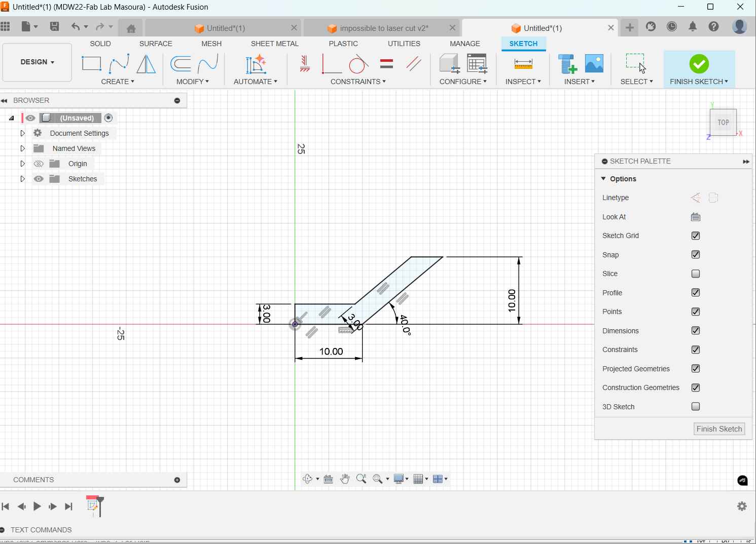
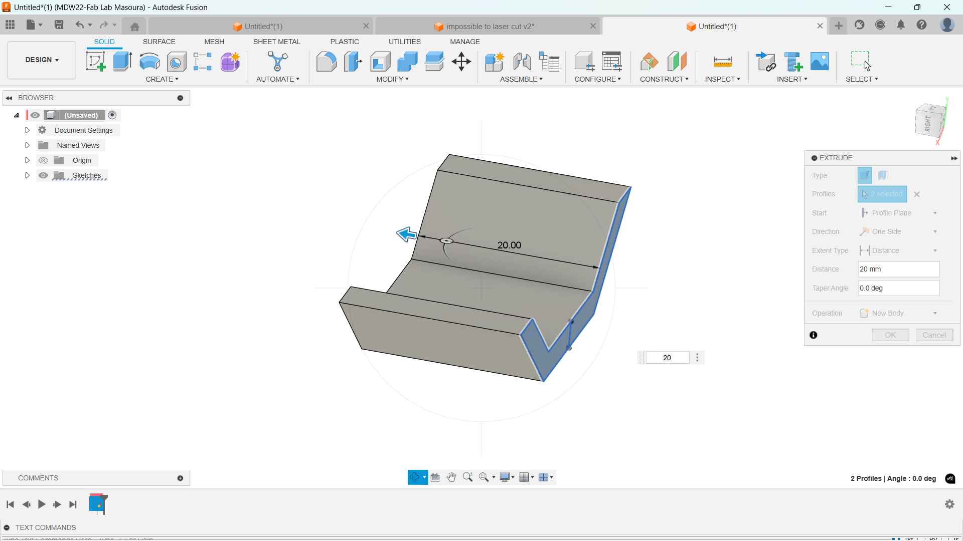
Created a sketch of the mesh's side profile I made the angle of the part at 30 deg based on the test I made in the group assignment
I mirrored the part and extruded.
-
Step 2
Then sketched on the angle side of the part to create the holes.
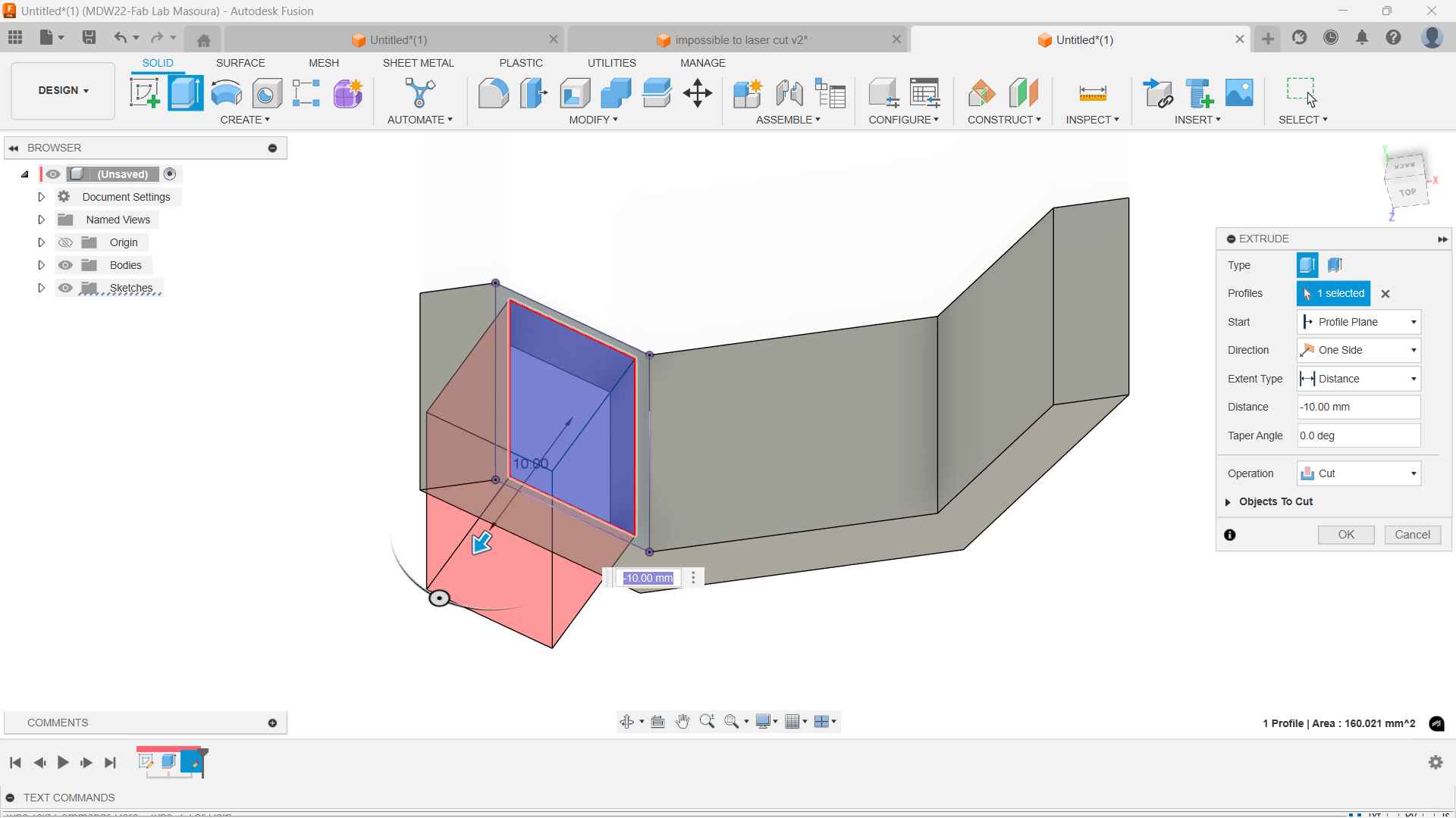
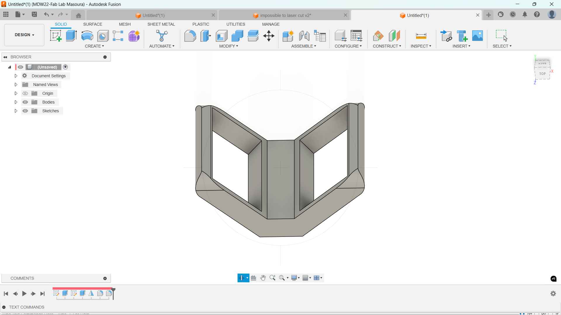
-
Step 3
Then the rest was moving the part to create however configuration I wanted. after that I didn't know how to export
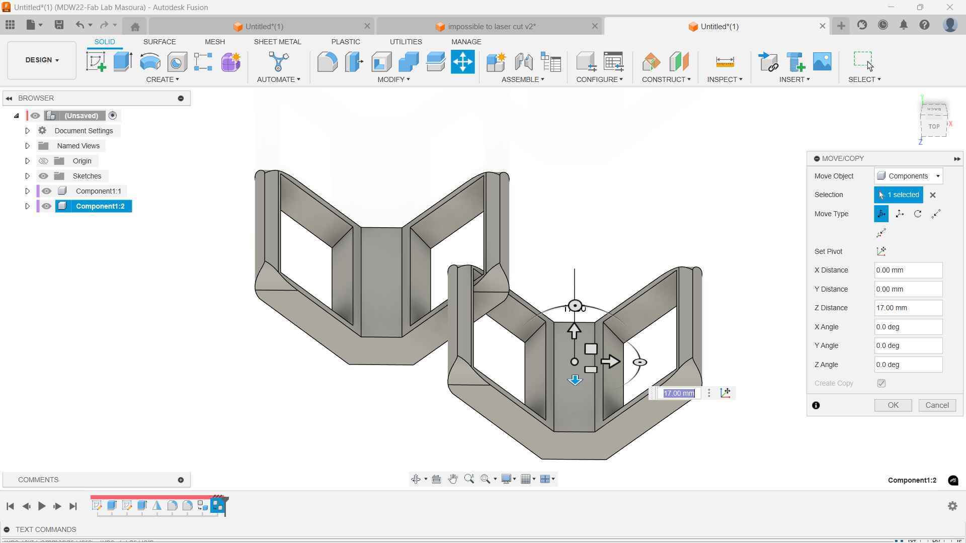
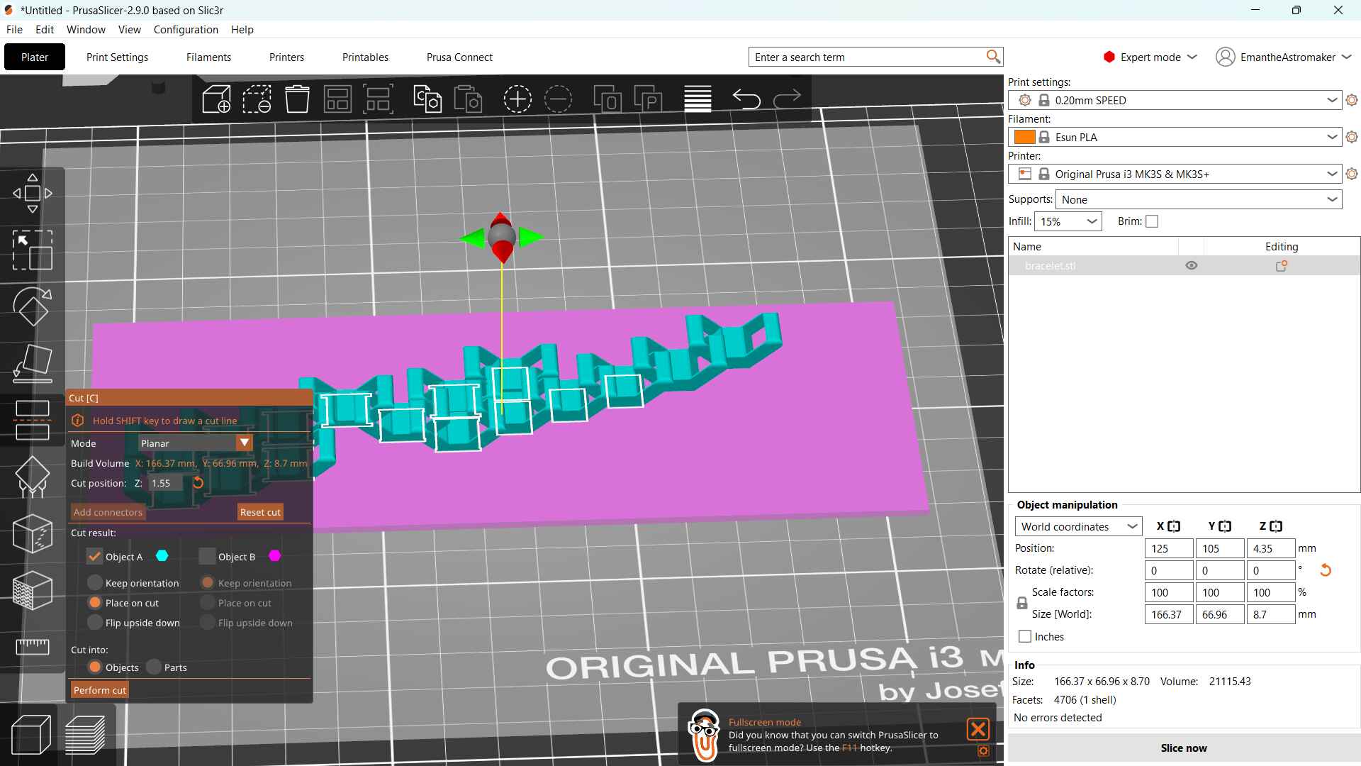
Fortunately, I read Amany's documentation and some suggested to her an interesting idea which is to create a thin boundary around the pattern this will connect them, then exported as Mesh Binary.
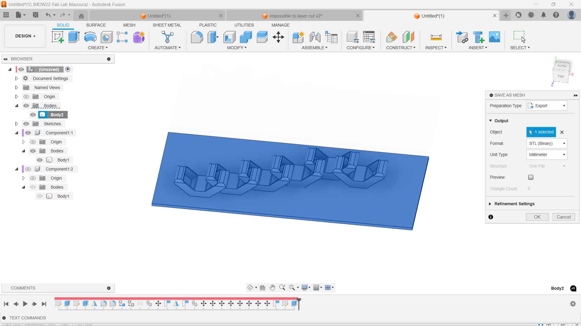
In PrusaSlicer I used the cut tool to cut the boundary.
Your new favourite Earrings

Full Control Gcode designer
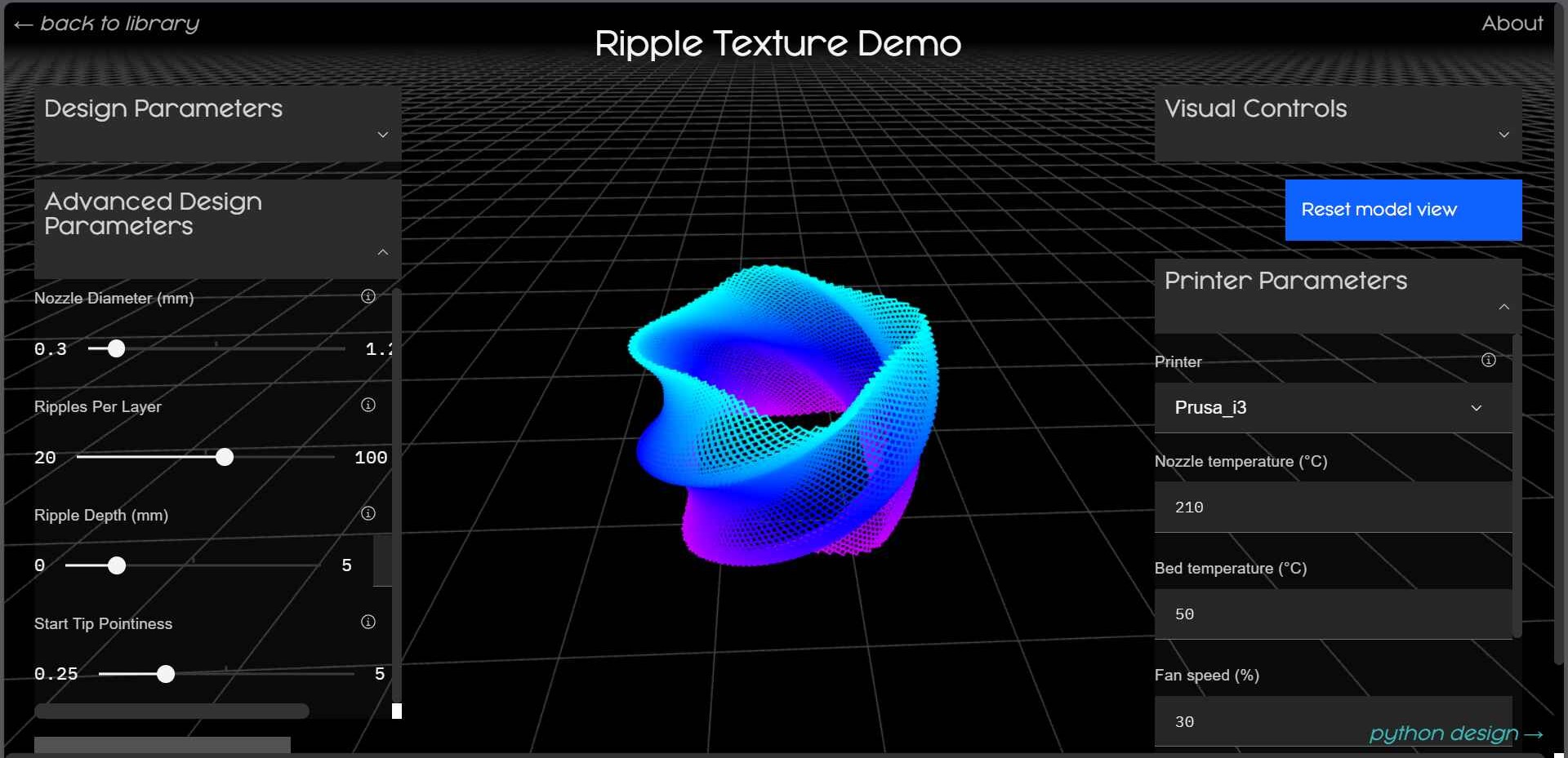
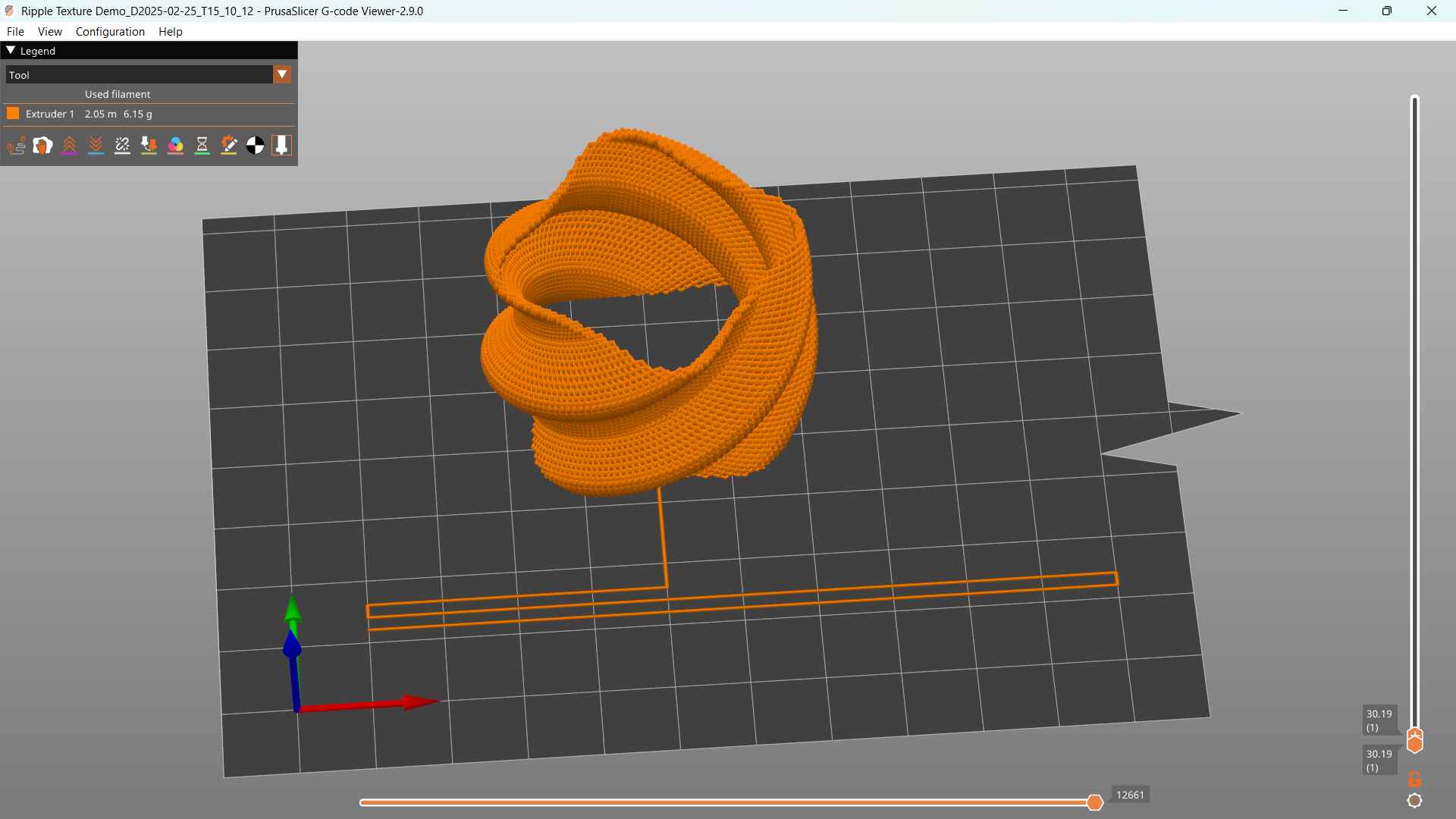
I wanted to play a little with the G-code and I had my eyes on FullControl Gcode for while. FullControl GCode Designer is an opensource free software that uses Excel to generate GCode. You write print paths similar to CAD but you can add in every line in the print path direction, speed, extrusion rate, acceleration to customize it to your heart's content. of course it can be parametric I didn't have the license of Excel on my laptop so I used the website version of the software. it has a pre-existing designs library that you can use to play around. I used the ripple texture design changed the Printer to "Prusa i3", and increased the number of ripples per layer, then exported the Gcode.
My Pride and Joy
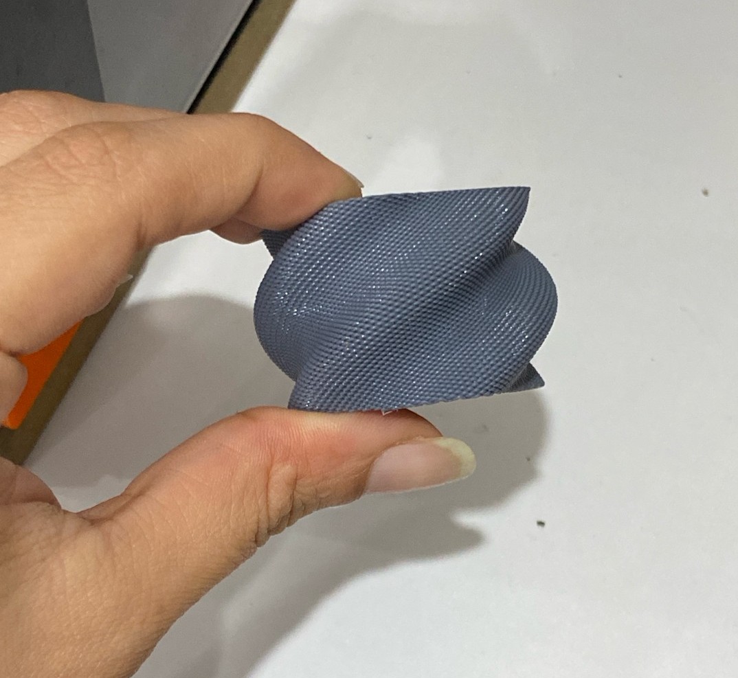
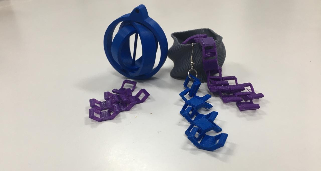
3D Scanning
Trial #1
Macintosh S3/30 with KIRI Engine App
Before Kinect we were urged to try 3D scanning with an app so I went ahead and searched for free 3D scanning apps and found KIRI Engine It's a free app that you can use to scan objects with your phone camera and allows up to export your designs up to 3 times. It uses your camera to take a picture of the object up to 100 photoes.
I really wanted to scan the Macintosh we hadat the fab lab. it's pretty old and no one seems to know where we got it from so it has a mysterious vide. And this was the final result! It was not that good!
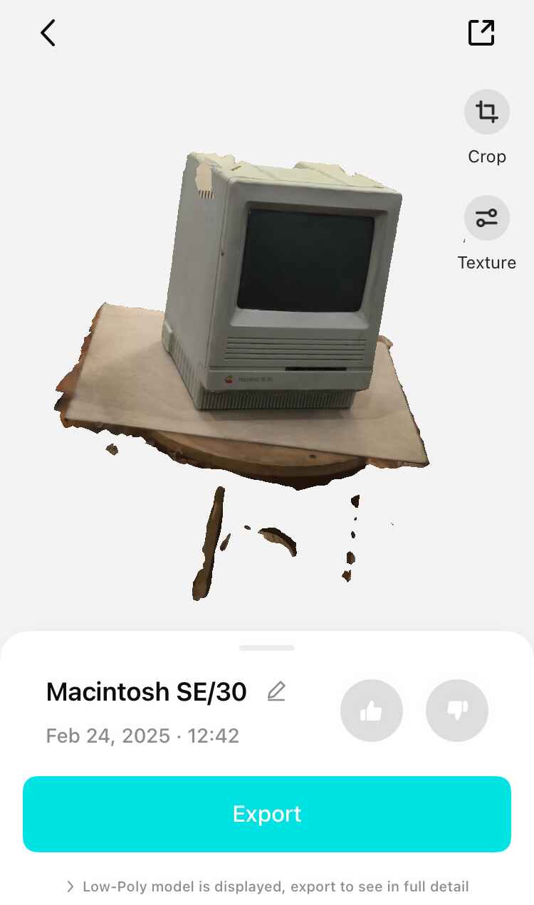
I uploaded the design to sketchfab to make a 3d view of it also the non-LowPoly design is huge, so I made it accessible for people to download and linked the low-poly in the files below to dodge push 107MB to the repo.hehe
Trial #2
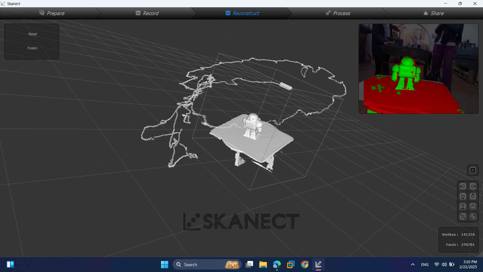
Makey with Microsoft SKANECT
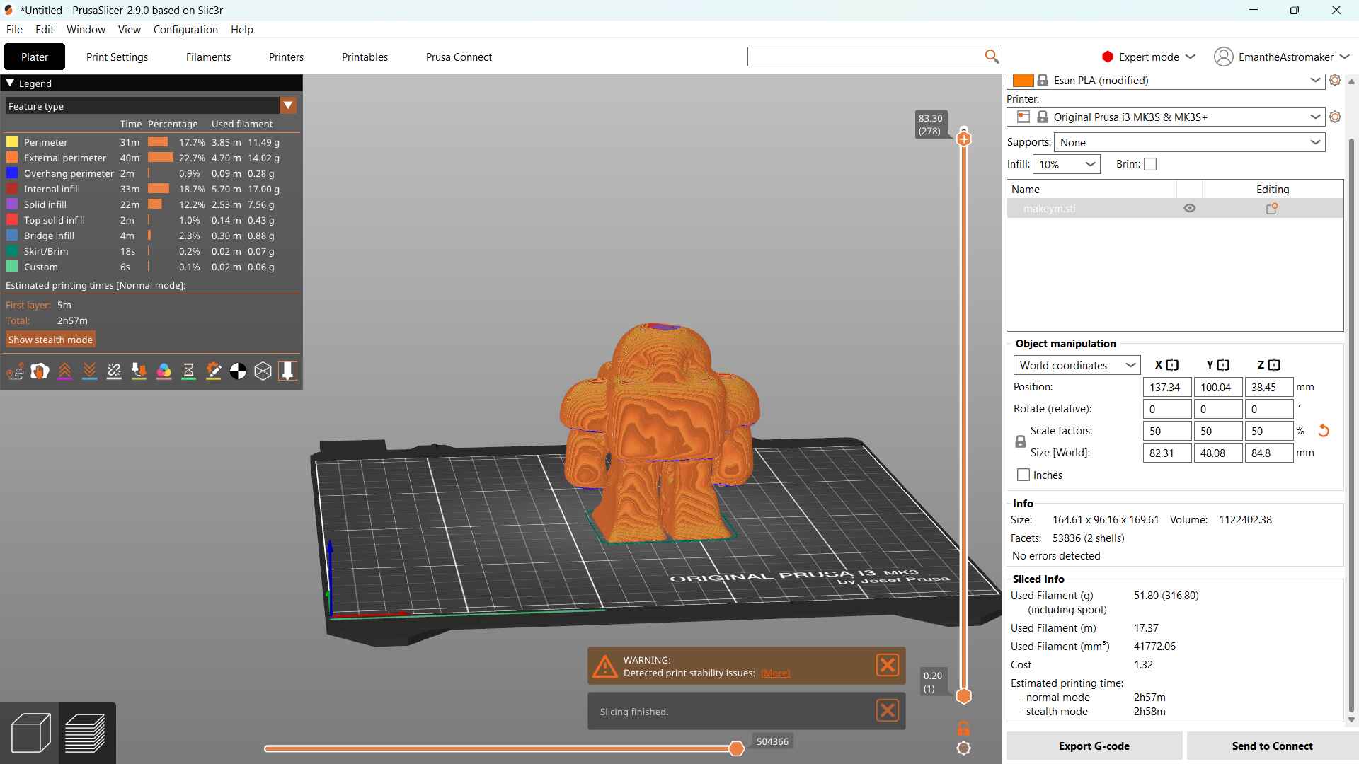
We got introduced to the Microsfor kinect which is a tool that used a 3D scanning technology called structured Light meaning it uses a laser to project a pattern on the surface you're pointing at, while the camera is recording how the pattern is changing because of the object. We took a tour in the Skanect software. and went a head to choose an object to scan. We had recently launched the date of Maker Fair Cairo and since it was the 10th edition we had a little special activity for gathering we made for the makers. We made Makey with plaster So I wanted to 3D scan it, Doaa made a paper boat and wanted to 3d scan it so I volunteered to 3d scan the really-small boat and she scanned really-big makey. I like to torture myself with challenges.
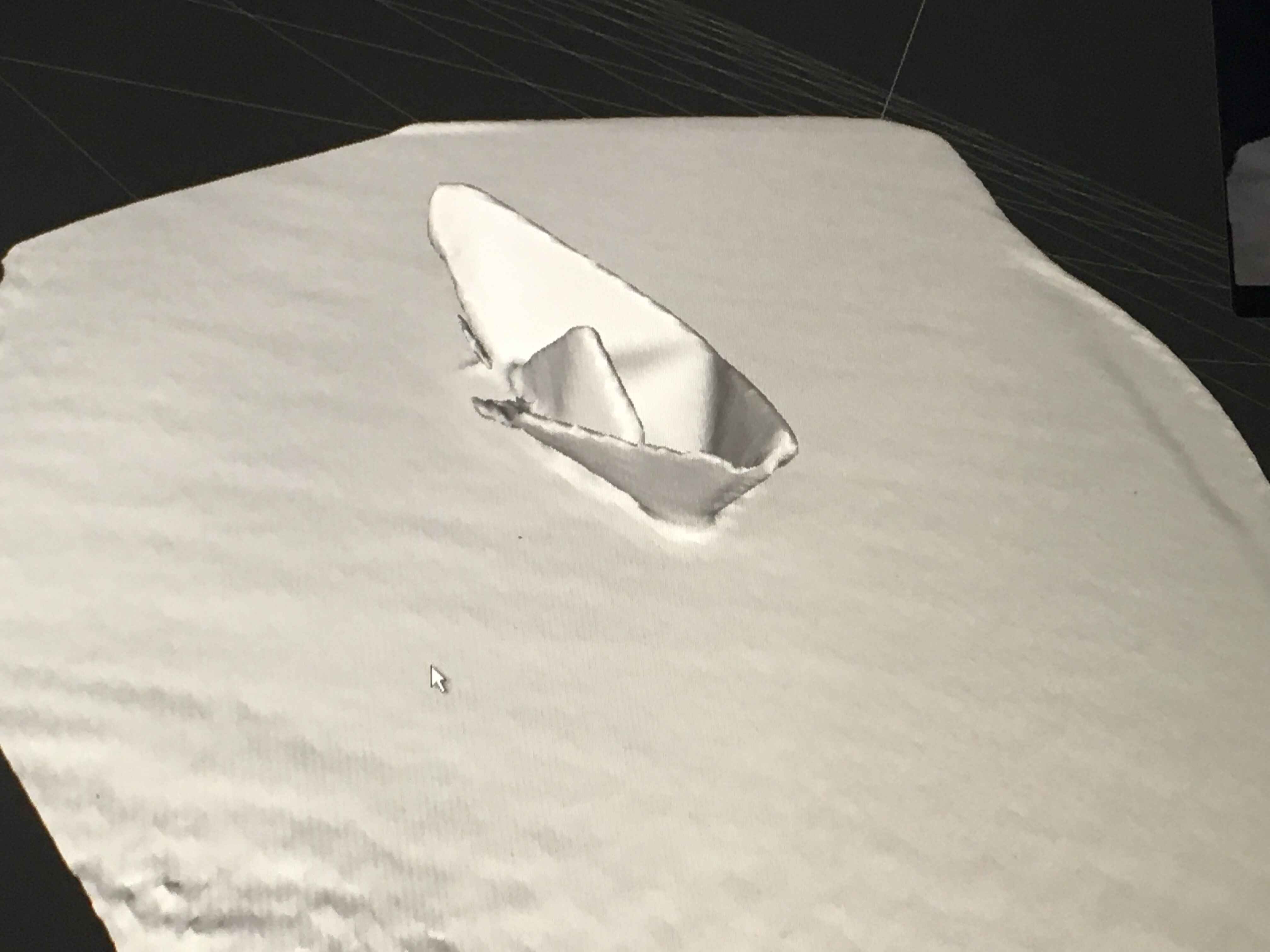
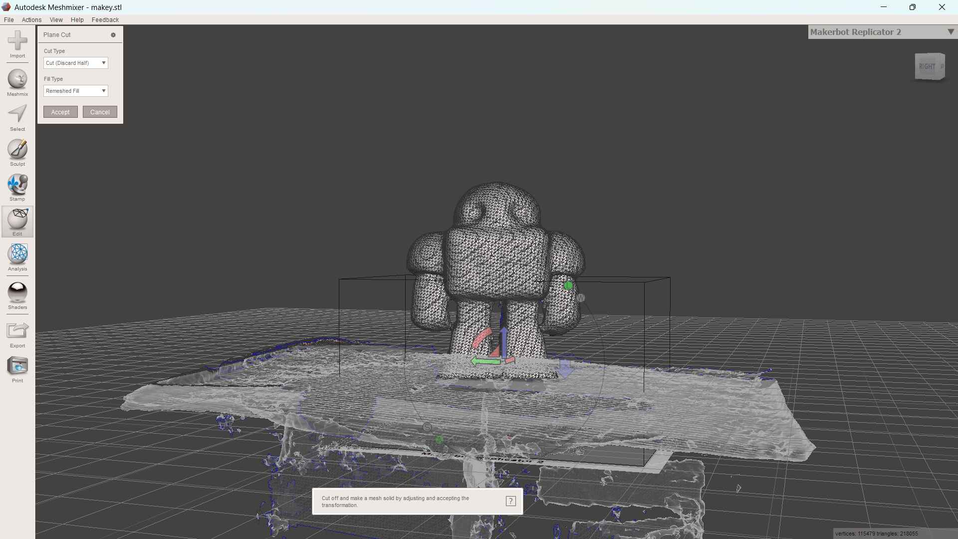
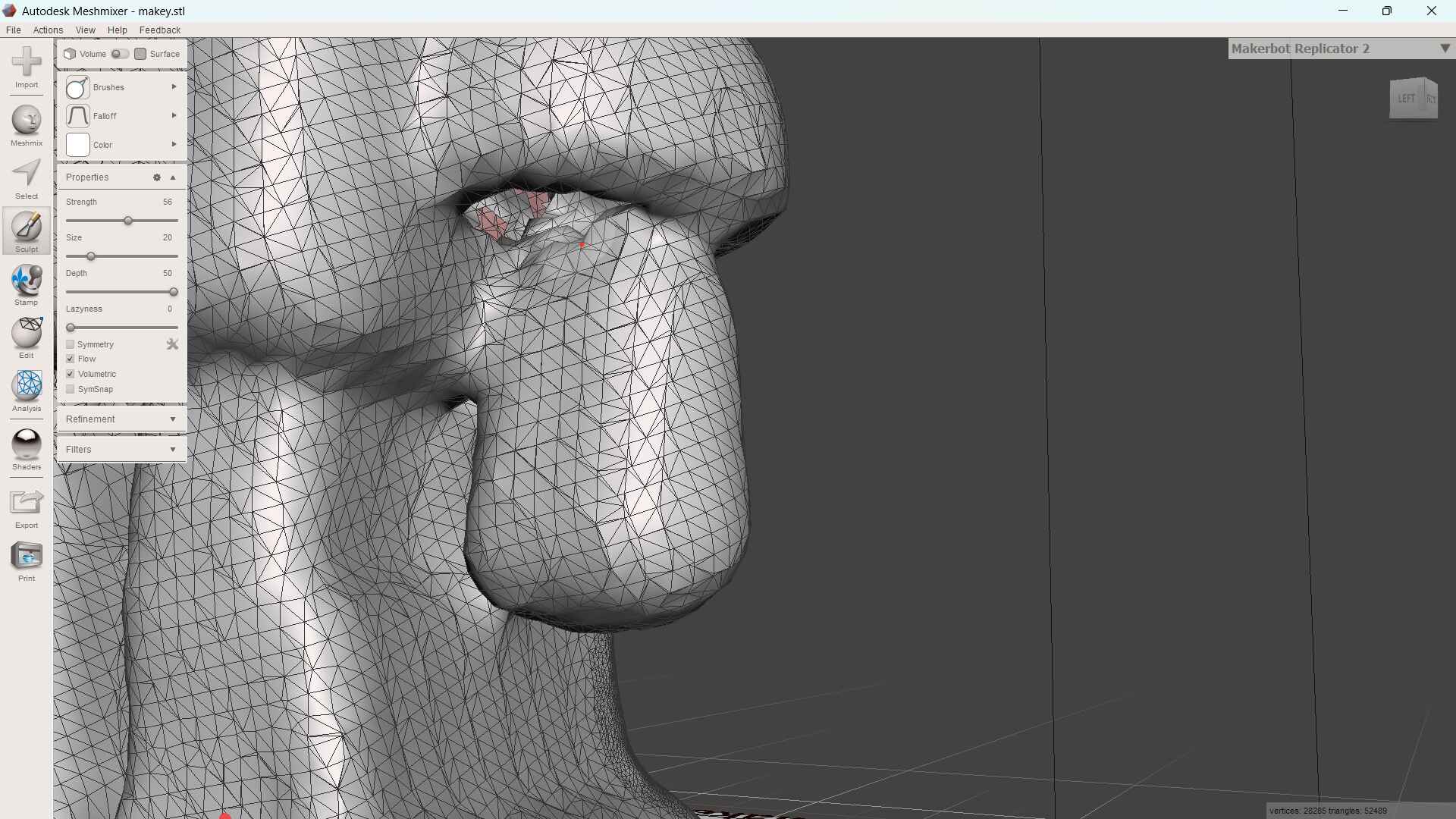
Meshmixer
I went to meshmixer to fix the stl after exporting it. I preformed a plane cut to cut the used the sculpt and used the move brush to fill the holes. Once I was done I returned to edit and used the maker solid tool.
